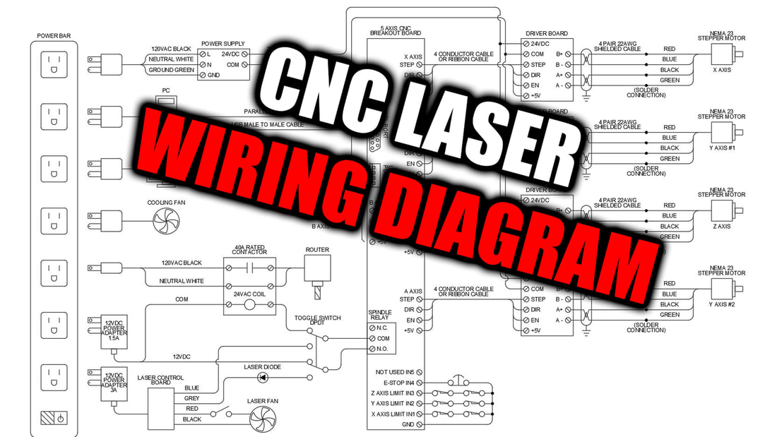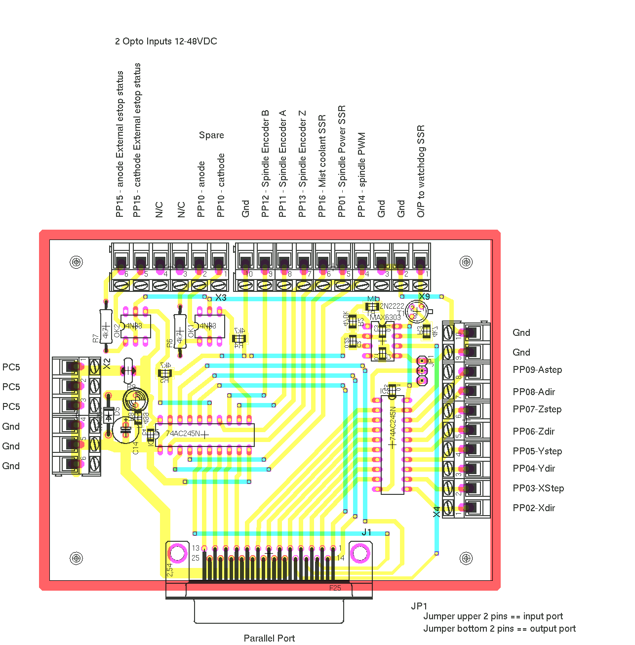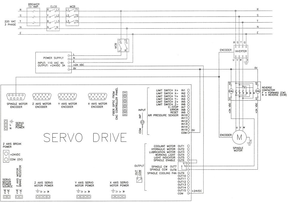
Electrical diagram of the CNC Machine. * Pinout details are given in
0-10V signal. GND +5V GND +5V V-V+. AD AP +5V ZD ZP +5V YD YP +5V XD XP +5V. motor driver. motor driver. motor driver X motor driver. stepper motor stepper motor stepper motor stepper motor.

simple cnc wiring diagram
FANUC CNC control units, as shown in the configuration diagram in Chapter 2, and supplies additional information on using these components with the Series 0i/0i Mate. Refer to individual manuals for the detailed specifications of each model. The models covered by this manual, and their abbreviations are:

cnc wiring diagram breakout
5 axis cnc breakout board step dir en +5v 24vdc com step dir en +5v b+ b - a+ a - driver board step dir en +5v 24vdc com step dir en +5v b+ b - a+ a - driver board step dir en +5v 24vdc com step dir en +5v b+ b - a+ a - driver board step dir en +5v in1 x axis limit nema 23 stepper motor x axis y axis z axis a axis x axis n.c. com parallel cable.

simple cnc wiring diagram
Miscellaneous CNC Documents. - Solid Model files for OAK, ALLIN1DC, PLCADD1616, DC1, ADD4AD4DA, Encoder Expansion Board. zip file. - CNC console dimensions and mounting examples. - CNC Standard Electrical Cabinet M400/M39/T400/T39. - CNC Standard Electrical Cabinet M15 upgrade.

XHC MKXV CNC Controller Mach3
TO GAIN ACCESS TO SW1 REMOVE OMI WINDOW AND LABEL. 2.INSTALL FOLLOWING ELEMENTS ON 1100-1 BOARD: FUSES AGC-2 - F10, F29, F40. SOLID STATE RELAYS (BLACK) - K16, K31. CIRCUIT BREAKER 2.5A - CB1 3.TO ACTIVATE THE PROBES USE THE FOLLOWING COMMANDS: MP12 PROBE - M64, M66 TS 27 PROBE - M65. OMI.

CNC Wiring PDF Business
1.1 Introduction. The latest upgraded 5 axis breakout board is specially designed for the CNC single axis 2-phase stepper driver controller, such as M542, M542H, MA860H, 2M542, 2M982, DM542(A), DM860(A) etc. single axis stepper driver controller series. With this 5 axis breakout board, any 1-5 single axis stepper driver controllers can be.

CNC Instructable Wiring Schematic [Download] e^CNC
32MP Control Wiring. 4th Axis Servo Options. Chip Conveyor. CNC 88-32MP E-Stop Circuit. DC Chassis WD. ELE-2064 Diagram. EMC.pdf. Fadal Servo Coolant Wiring Diag. Fadal Wiring Diagrams. GE Fanuc 18i Wiring Diagram. Hall to Reed Sw Conversion. Legacy WD. Legacy Wiring Diagrams. Miror plug wiring. Options. Pendant. Probes and Scales. Servo Turret.

cnc wiring diagram pdf Wiring Diagram and Schematics
Learn how to install and configure Mach3Mill, the software that controls your CNC machine, with this detailed PDF guide. Find out how to set up the printer port, the motor tuning, the inputs and outputs, and more.

Our CNC Table
P12 5V GND P11 GND P15 P13 P10 12V GND GND P16 P17 P4 P5 P6 P7 P8 P9 GND GND 5V 5V GND P2 P3 P14 0-10V PWM(P1) P3 COM P2 COM P4 COM 15-32VDC Current MicroStep Typical driver PUL+ PUL-DIR+ DIR-ENA+

EMCO Compact 5 CNC Electrical Wiring Diagram
There are 3 main components needed to get the CNC Shield up and running, 1) CNC Shield; 2) Stepper Drivers, and; 3) Arduino UNO. Each of these will be mentioned below. Version 3.0 of the CNC Shield is used throughout this guide. The CNC Shield is licensed under a Creative Commons Attribution-ShareAlike 3.0 Unported License.
Mach3 Cnc Wiring Diagram Wiring Diagram
Step 1 Suggested cable lengths Cable lengths included in the kit assume that the controller will be installed at the back of the machine. You may need to source different lengths of cable if you have other plans for controller placement. Your kit ships with 2 long length cables, one with 3 conductors, one with 4 conductors.

Cnc Breakout Board Wiring Diagram
Page 9 Step4 X-Z Axis Assembly Installation Note: 1. First fix the coupling to the 42 stepper motor, and then fix the 42 stepper motor to the bakelite-C. 2. First fully insert the spring and brass nut into the Z-X axis assembly, and then tighten the X screw. Step5 Bakelite-D Installation. Page 10 Completed Step6 Spindle Installation.

Cnc Breakout Board Wiring Diagram
Cnc Wiring Diagram - Free download as PDF File (.pdf), Text File (.txt) or view presentation slides online. plano electrico

Cnc Wiring Diagram Endiaries
1、Unit select。 Select unit:on menu"config"—select native units--- select MM. BlueSky_TEC Mach3 5 axis CNC interface board (BL-MACH-V1.1) instruction 2、Ports and pins: (1)、Port setup and axis selection:note--make sure you have save your changes. (2)、Motor outputs:set as the below diagram。

FileBasiccncwiringdiagram.jpg TechnoDocs
DrufelCNC - software for controlling CNC machines. Read more: https://drufelcnc.com NOTICE OF LIABILITY Using any CNC machine is a dangerous operation. All precautions must be taken, as the machines may turn on at any time, the software MAY malfunction at any time, any user of the Software must understand and take this into

Cnc Machine Circuit Diagram
Go to the new parallel breakout board to get more information and the wiring diagram. cnc electronics - main power supply Share Watch on Beginning with only one driver and motor eliminates most of the complexity that typically scares the timid folks out there. But first, the power must be establish.